


 | Stepper Motors   |
Stepper motor manufacturers as well as end-users of stepper motors benefit greatly from the ability to measure and analyze the characteristics of a stepper motor/driver.
The measurements below were obtained by connecting an encoder to the shaft of a stepper motor, and monitoring the encoder and stepper-motor indexer signals using the Stepper Motor Dynamics Analyzer. The Stepper Motor Dynamics Analyzer provides a means to quickly:
These measurements can also be made with the Motion Capture Card using LabVIEW® drivers or the SensorPlot capture and analysis software.
| Static Step Accuracy The graph on the left is showing the min, max and average step response position accuracy measured over one revolution. The arrows indicate the peak to peak static step accuracy at a point where the motor shaft has settled.  |
| Micro-step Accuracy  |
| An unloaded stepper motor (micro-stepped 16:1) was ramped in velocity up to five Revolutions Per Second. At low velocities, resonance caused the velocity of the motor to fluctuate severely. At higher velocities (above the resonance frequency of the motor), the velocity became smoother. Idle detent torque excited the resonance even when micro-stepping was employed. | 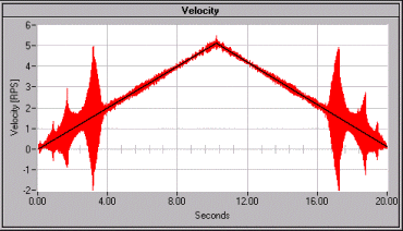 |
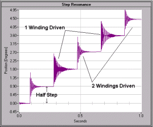 | Stepper motors resonate even when stepped very slowly. In this case, the motor was stepped at a rate of one-half step every 200mS. Notice how the motor resonates almost a full step (1.8°) after each half step. The frequency of the decaying resonance can be used to estimate the holding torque of the motor. |
| The graph to the right is plotting step position error (dynamic position error) versus velocity. The shaft of a stepper motor will lag behind the ideal step position in the presence of a torque load. In this case, the torque load (friction) increased with velocity causing the shaft to lag more-and-more as the velocity of the motor was increased. | 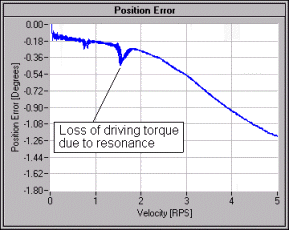 |
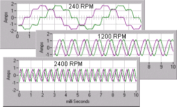 | The performance of a stepper motor is strongly dependent upon the driver. As the velocity of a motor increases, the driver's ability to deliver current is impeded by the back EMF of the motor, the non-zero inductance of the motor windings, and the rail voltages applied to the driver. The diminishing current results in a loss of torque and a reduction in dynamic accuracy. |
| Stepper motors skip. In the graph to the right, the ideal and measured shaft positions of a 0.45° motor are plotted on the left Y-axis while the difference is plotted on the right. Ideal shaft position is measured by connecting SensorPlot™ to the step command of the stepper-motor indexer. This motor skipped 9°. | 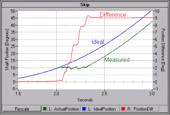 |
Euclid Research · 2 North 1st Street, 6th Floor · San Jose, CA 95113-1201
Tel: (408) 283-9020 · Fax: (408) 283-9029