 SensorPlot™ Overview SensorPlot™ Overview
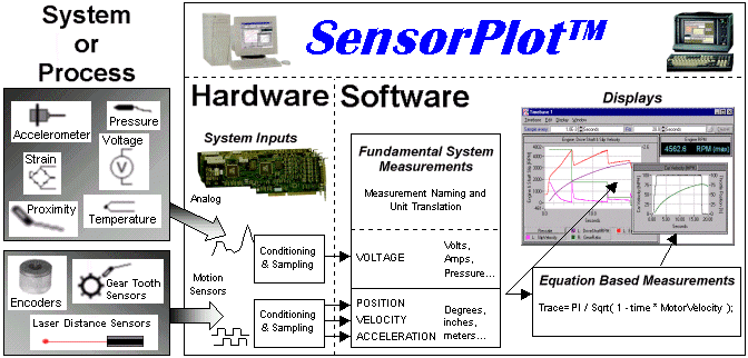
What is SensorPlot™
SensorPlot™ is a general instrument intended for use in the study, characterization and analysis of mechanical motion and related parameters. SensorPlot™ runs on a Windows® platform and integrates motion sensor inputs, analog inputs, a sampling and triggering subsystem, equation-based measurements, and a complete set of analysis and data exploration tools. The motion sensor inputs are specifically designed to connect to optical incremental encoders and other motion sensors, and allow users to make accurate, high-speed measurements of angular/linear position, velocity and acceleration concurrently with analog measurements like voltage, current, and pressure. Measurements are plotted on a variety of graphical and numerical displays and can be manipulated using arbitrary mathematical expressions in real-time.
Measurements
SensorPlot™ supports 4 fundamental measurements: position, velocity, acceleration and voltage. These basic measurements, called measurables, can either be displayed directly or included in equations, called traces, to form more complex measurements. Traces are like virtual channels that serve to extend the measurement capability of the system. Trace equations typically consist of one or more measurables but can also be mathematical expressions having little to do with measurements. Two example traces are given below:
| Trace Name | Trace Equation |
| GearRatio | trace=engine.vel / wheels.vel; |
| TheoreticalAcc | trace= exp( -time/0.003 ) * (1 - exp( -time/0.028 ) ); |
The trace named GearRatio can be used to measure the gear ratio of a transmission in real time. The equation is constructed by taking the ratio of two measurables: the velocity of the encoder named engine, and the velocity of the encoder named wheels.
The second trace named TheoreticalAcc has little to do with making measurements but rather approximates the theoretical acceleration of a DC motor. The equation for the trace named TheoreticalAcc is constructed using a system variable called time which takes on the values of the sample times of an acquisition. A likely use for the trace TheoreticalAcc would be to plot it with an actual measured acceleration to assist in exploration and analysis.
Acquiring and Displaying Data
Data that is acquired and computed is presented in displays that inhabit a Window called a Timebase. A Timebase controls the acquisition of data and updates in real time any number of numerical and graphical displays that coexist within a Timebase window. The rate at which samples are acquired, and the length of an acquisition are independently controlled using any of the resources available in the system. The sampling rate of a Timebase can slaved to:
The length of an acquisition can be independently governed by:
Consequently, the sampling model of a Timebase can be generalized as: Sample every M seconds, degrees, or counts of an external event for N seconds, degrees, counts of an external event or samples. For example, the position of a motor and a pulley can be sampled every 3mS for 6 revolutions of the motor.
Like an oscilloscope, SensorPlot™ supports the addition and removal of traces during an acquisition. Traces that are added during an acquisition, automatically join the traces already being displayed. Traces that are removed, automatically disappear. The effects of editing a trace equation are instantly reflected by the displays. The dynamic nature of the traces permits immediate analysis and investigation of acquired data thus avoiding the delay of off-line analysis. To assist in the exploration of data, all graph and spectrum displays are equipped with their own set of quick analysis functions.
Triggering Acquisitions
Although a Timebase can be manually operated to acquire blocks of data called sweeps, connection of a Timebase to an advanced trigger system, called the Main Trigger System, facilitates the acquisition of sweeps in a more controlled fashion. The Main Trigger System provides simple triggering like start sampling now to more complex mechanisms like start sampling when engine is started and acquire a block of samples every time the brake pedal is pressed. Using the same sample control resources available to all Timebases, the Main Trigger System issues start commands based on time, an external event, or the position of an encoder.
Saving Configurations
Because SensorPlot™ uses a unique name concept to manage the instruments within the system, the system can seamlessly grow (and shrink) under applications that have already been created and customized to suit an application. Configurations can be saved on disk and retain all information about the application including window positions, display configurations, trace equations, Timebase sampling parameters and input configurations (e.g. interface, termination, and so on). Saving all configuration information in the file allows users to create canned applications.
Acquired data can be saved with the configuration file to allow the data to be analyzed at a more convenient time or place. The software can be operated in a stand alone, no-hardware mode, on a separate computer allowing the analysis to be continued at a more convenient time or place. Data that has been acquired and displayed can also be exported for analysis by other applications.
| Motion Sensor Inputs The motion sensor inputs are designed to directly connect to three types of sensors/signals: sensors that produce a single pulse per incremental move, sensors that produce quadrature signals (A quad B), and step and dir signals. Such sensors include optical incremental encoders, gear tooth sensors (proximity sensors), photo reflective sensors, photo-interrupters and laser interferometers. SensorPlot™ can also be unobtrusively connected to many servo and stepper controllers since they often provide the appropriate signals indicating commanded or sensed motion. Analog Inputs The system also has analog inputs for measuring voltage produced by such sensors as voltage, current, pressure, and accelerometer transducers. Synchronous measurement of analog signals with measurements of motion ensures time correlation of captured analog and rotational/linear motion phenomena. Keep Simple Things Simple SensorPlot™ is designed to be easy to use and requires no programming. With a single click of a mouse button you can freeze measurements on a display for later reference, duplicate or filter measurements, create variable persistence effects, and accumulate trace minimums, maximums, and averages. Add and resize displays, change trace colors and quickly access tools without being subjected to a labyrinth of menus and options. Interactive Exploration To facilitate data exploration, new equation-based measurements can be created and displayed without re-acquiring data. Existing equations can be edited without losing data during or after an acquisition. A number of exploration tools are available including a general data fitting tool that allows data to be fit over specified regions using arbitrary mathematical expressions. Using an interactive statistics tool, a number of statistics can be computed and highlighted over a user-specified range. Cursors can be used to make measurements, to define regions of analysis and to zoom an area of interest. Sophisticated Analysis on Demand The analytical power of SensorPlot™ does not stop with acquisition and display of data. The system supports a number of spectral analysis functions, displays and tools that permit interactive frequency domain analysis using different ranges, averaging methods and windows. Tracking filters assist in identifying and removing phenomena that varies with time, position or some other parameter. Synchronous time averaging permits detailed vibration analysis. This sophistication can be experienced on an as needed basis, and is supported by On-line help and numerous wizards. Save It For Later System configurations can be saved with or without data for later recall making it convenient to repeat an experiment. In addition, the same system software runs without instrumentation on a different computer permitting post-acquisition analysis to occur at a more convenient time and location. Data can be easily exported in a variety of formats allowing the system to interact with other applications. | Measurements The measurement model of the system is very simple. All inputs are automatically sampled at user defined sampling rates. Analog inputs are scaled to user defined units. Motion sensor inputs automatically provide measurement of position, velocity and acceleration. You can display these measurements directly or define custom measurements using equations written in standard mathematical notation. Equations are evaluated in real-time allowing you to perform such things as scaling, complex arithmetic, and inter-channel analysis as data is being acquired. Choose from standard math operators, multi-frame functions, statistical and logical operators, complex arithmetic, as well as such operations as integration, differentiation and filtering. Equations can reference the results of other equations as a means of reducing mathematical complexity and computational cost. The system supports a variety of display types including graphical, spectral, numerical and statistical table displays. Displays can coexist in any number with each display presenting one or more measurements. Motion Capture Hardware Measurements of angular/linear position, velocity and acceleration are accomplished using a Motion Capture card. It uses custom integrated circuits, high speed FIFOs, and Edge Time Capture technology to make fast/accurate measurements of position, velocity, and acceleration independent of encoder resolution. The motion capture card also implements the distributed advanced sampling sub-system. Analog Capture Cards Analog measurements are obtained using 16-channel analog cards. 12bit (1MS/S) and 16bit (100kS/S) cards are available to suite particular needs. The range of each analog channel is independently controlled with each channel supporting a maximum input range of +/-10V. Channels can be independently paired to accommodate differential measurements. Accuracy and Speed to Spare The system can sample both analog and motion sensors at speeds up to one MegaSample/Sec covering the most demanding mechanical measurement applications. The Edge Time Capture technology facilitates accurate velocity and acceleration measurements at any RPM. For example, the angular velocity of a shaft rotating at 3000 RPM can be measured with an accuracy of 0.02% when sampling at a 1 millisecond-sampling rate. When sampled once per revolution the accuracy of the velocity measurement improves to 0.001%. The motion sensor inputs can accommodate the fastest available encoders allowing measurements of velocity in the hundreds of thousands of revolutions per minute. At the same time, velocities as low as one revolution per hour can also be measured with great accuracy. Ordering Users typically purchase a hardware/software package installable in a user supplied PC. A basic system includes the SensorPlot™ software, one or more motion capture cards (each supporting up to four motion sensors), cables, and connectors. Analog cards are optional and support 16 channels each. The system channel count is expandable and limited only by the available slots in the PC. The SensorPlot™ can also be shipped complete in a mini-tower Pentium PC or portable lunchbox platform. |
Euclid Research · 2 North 1st Street, 6th Floor · San Jose, CA 95113-1201
Tel: (408) 283-9020 · Fax: (408) 283-9029