

 | Some Rotational Measurements of a 3-Phase Induction Motor   |
SensorPlot™ can be quickly connected to motors, controllers, actuators and the like to perform preventative maintenance checks and evaluate the performance of newly commissioned or existing pieces of equipment.
Below are a few examples illustrating some measurements made on an industrial motor using SensorPlot™. The data for the graphs below was taken on a 500 hp induction motor controlled by a 480V variable frequency drive. The motor was connected to a gear box (5:1 gear ratio) which was driving a large inertial load. The shaft velocities of the motor and gearbox were sensed using a capstan/encoder assembly placed against each shaft. The 3-phase voltages and currents generated by the controller were also measured concurrently with the shaft velocities.
 |
|
Motor Startup/Shutdown Sequence
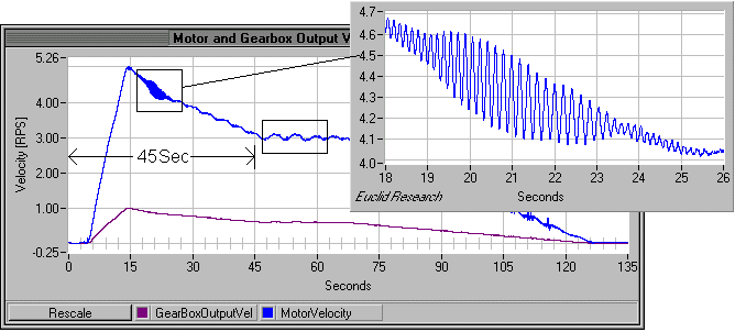
SensorPlot™ was used to monitor the shaft velocities of the motor and the output of the gearbox. As illustrated in the startup shut-down sequence below, the motor exhibited a substantial overshoot before settling to its programmed velocity of 3 RPS (180 RPM). The overshoot indicated that there was potential loop tuning problem. Also of interest was the resonance that occurred when the controller attempted to compensate for the overshoot. Lastly, there appeared to be a slow periodic velocity variation at the programmed velocity of 3 RPS.

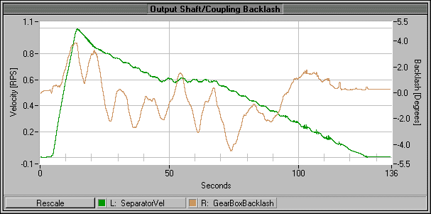
Gearbox backlash was measured by subtracting the output shaft angular position from the input shaft angular position (normalized by the gearbox gear ratio). The gearbox/output shaft coupling combination exhibited a peak backlash of 4°.

Velocity Ripple, Power and Friction Measurements
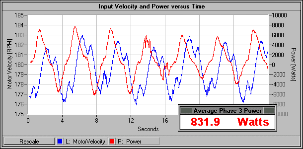
With the motor/gearbox unloaded (only driving an inertial load), the motor was programmed to run at a constant velocity of 180 RPM. During this run, the 3-phase voltages and currents generated by the controller were measured concurrently with the shaft velocities. From the simple measurements of velocity, voltage and current, several observations were made.

Power Delivered / Energy Stored
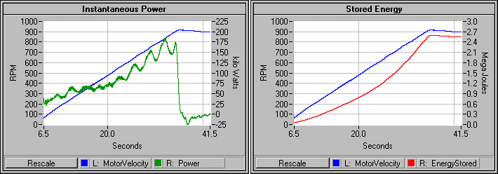
The power delivered to the motor and the energy stored by the inertial load were computed mathematically from the measured voltages, currents and motor shaft velocity. The stored energy was of particular interest because dynamic braking was used to decelerate the load. Subsequently, the deceleration rate was dictate by the rate at which the controller could absorb energy and amount of mechanical energy stored in the system.

Euclid Research · 2 North 1st Street, 6th Floor · San Jose, CA 95113-1201
Tel: (408) 283-9020 · Fax: (408) 283-9029