 Two Dimensional Scanned Sensor Data Acquisition Sampler
What is the 2D Mapper
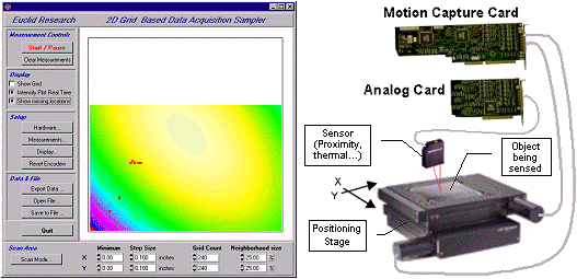
A 2D Scanned Sensor system consists of a positioning stage, a sensor of some type, and a specialized data acquisition system. An object is moved relative to a sensor (or a sensor relative to an object), the sensor output is measured at a number of precise locations (typically on a grid), and a 2 dimensional map of the measurements is created, displayed, and manipulated.

| Possible Measurements | Surface profile - Surface roughness - Structural integrity - Micro cracks -Stress distribution - Residual stress - Reflectivity - Color Uniformity - Magnetic properties - Dieletric properties - Electric field distribution - Surface electric current - Surface velocities of liquids |
| Possible Sensors Types | IR temperature sensor - Capacitve or inductive probe - Optical distance probe - Eddy current probe - Laser Triangulation sensor - Laser confocal - Ultra sound - X Ray Sensor - Color sensor - Spectrophotometer - Scattered light Photonic - Reflected Light Sensor - Polarized light sensor - Laser Doppler Vibrometer |
System Components
| Supplied by Euclid Research | Supplied by User or by Euclid Research |
- Motion capture card: Connected to the stage encoders or stepper motors. Tracks position and triggers measurements on analog capture card.
- Analog capture card: Connected to the sensor[s], makes the actual measurements.
- Scan2D software: Controls the capture cards, coordinates the measurements, displays the results.
| - Personal Computer: Running Windows 95/98.
- XY or R/Theta Stage: Has 2 encoders or/and 2 stepper motors. Moves and senses the motion of the sensor or of the object. Could be manual or motorized.
- Suitable sensor[s]: Analog voltage output sensors whose output is proportional to the phenomena being measured and mapped.
|
We can provide you with some or all the tools you need to build your own, or we can supply you with a complete ready-to-run system built to your specifications.
Hardware Features
- Choice of using incremental encoders or the 'step and direction' signals of a stepper motors to track position.
- Programmable support of all types of incremental encoders with all common types of interfaces and resolutions.
- Programmable analog inputs with several ranges up to +/- 10 volts available in 12 or 16 bit resolutions.
- Multiple analog channels allowing measurement of several sensors at once.

Software Features The Scan2D software support the following features and allows the user to:
- Specify the type of stage XY or R,Theta
- Specify the encoder resolution, the range and units of measure of the analog sensor[s]
- Specify coordinate unit translations and positive direction of movements.
- Reset the encoders to specify a home position or a reference mark.
- Specify a scan area and grid spacing for each direction.
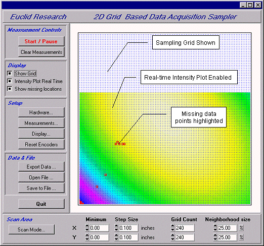
- Specify the color map method and values for an intensity plot.
- Specify a neighborhood region around each grid point where measurements should be taken.
- Start/Pause/Resume data capture, whereby measurement are taken when the encoders indicate that the sensor is within the neighborhood region of a grid point within the scan area.
- Specify what to do with repeated measurements over the same grid point: Replace, Average, Ignore, etc.
- Measurements can be made independent of nature of movement of the sensor. The sensor can moved in any pattern and enter and exit the scan area without affecting the measurements.
- See an interactive (live) display of the data points as they are taken.
- Highlight any missed measurement points on the display, allowing the user to go back and complete any missed measurements. This is useful for manual scanning operations.
- Clear all measurements and restart any time.
- Save/Load the setup and partially completed measurements to / from a file. This allows you to pause a measurement and continue at a later time/date.
- Export data for use by other data visualization and analysis programs.
Notes regarding positioning stage (XY Or R, Theta stage):
The purpose of the positioning stage is to provide a relative motion between the sensor and the object being mapped. One can arrange for a moving sensor and a stationary object or a stationary sensor and moving the object. Additionally, the actual scanning movement can either be manual (moved by hand) or automated (using a motion control system). In all of these cases, the relevant design aspect is the ability to sense and track the relative location of the sensor. There two methods that are supported by the motion capture card:
- The incremental optical encoder method: As part of the positioning stage, two encoders coupled to axis of motion. The system supports both linear and rotary optical encoders of any resolution. This approach is suitable when the encoders are included in the stage as part of motion control feedback. Manual stages can be fitted with such encoders easily.
- Stepper motor signals method: In stepper motor driven stages, the system can use the 'step and direction' signals that drive the stepper motor driver. These signals can be tracked to indicate the relative position of the sensor. Stepper motors typically move 1/200 of a revolution per step in full stepping mode and can be usually microstepped to provide much higher resolution. This resolution is further multiplied by the lead screw pitch to achieve very respectable linear movement resolutions.
Euclid Research · 2 North 1st Street, 6th Floor · San Jose, CA 95113-1201
Tel: (408) 283-9020 · Fax: (408) 283-9029
 Two Dimensional Scanned Sensor Data Acquisition Sampler
 Two Dimensional Scanned Sensor Data Acquisition Sampler
