 Motion Sensor Reference
 Motion Sensor Reference
Below is a summary of the many sensors available for measuring distance, rotation and velocity. Many motion sensors produce a digital output pulse in response to an incremental movement of an object. For these sensors, position information is derived by counting pulses and knowing the equivalent distance spanning two pulses. A few of the sensors like incremental optical encoders and laser interferometers provide information indicating the direction of the object in addition to its position.
Other sensors provide an analog output that is proportional to linear distance. Such devices include: laser triangulation systems, and some proximity sensors.
Sensors with digital pulse outputs can be directly connected to the Motion Capture card. Similarly, analog output sensors can be connected to the analog capture card of SensorPlot™.
| Sensor (signal) | Indicates Direction | Output | Rotational or Linear | Notes |
| Optical Incremental Encoders | Yes | Digital (Quadrature) | Both | Best accuracy, speed for a reasonable price. Encoder optics are enclosed providing protection from the environment. An encoder must be attached to an object to sense motion. |
| Interrupters | No | Digital (Single Pulse) | Rotational | Small and inexpensive non-contact sensors. Require alignment. Sensitive to dust and humidity. |
| Photo-reflective sensors | No | Digital (Single Pulse) | Linear | Provide simple non-contact sensing of shafts and rotating objects. |
| Proximity and Hall Effect switches | No | Digital (Single Pulse) | Rotational | Small and rugged non-contact sensors. Insensitive to oil, dirt, humidity and dust. Require a salient object to trigger the sensor. Gear teeth provide a natural stimulus for certain proximity sensors. |
| Laser Interferometers | Yes | Digital (Quadrature) | Linear | Best accuracy. Non-contact sensor that uses reflected laser light to measure the distance to an object. Used to make accurate linear displacement measurements. |
| Triangulation Sensors | Yes* | Analog | Linear | Relatively inexpensive non-contact linear motion sensor that uses reflected laser light to measure the distance to an object. Not nearly the accuracy of a laser interferometer. |
| Magnetostrictive Sensor | Yes* | Analog or Digital Pulse | Linear | |
| Ultrasonic Detector | Yes* | Analog | Linear | |
| Cable Extension Transducers | Yes* | Analog or Digital | Linear | |
| LVDT Sensor | Yes* | Analog | Linear | |
| Tachometer | No | Analog | Rotational |
* Direction can be derived by looking at the slope of the analog signal produced.
Incremental Optical Encoders
 Optical incremental encoders are linear/angular position sensors that use light and optics to sense motion. Because optical encoders can provide position information at high speeds, they are typically found in position and velocity feedback systems. For example, optical encoders are often found in motion control systems, machine tools, printers and plotters, material handling equipment and textile machines.
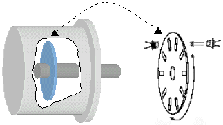
Most rotary optical encoders consist of a glass disk with equally spaced markings, a light source mounted on one side of the disk, and a photo detector mounted on the other side. The components of rotary optical encoders are typically packaged in a rugged enclosed housing protecting the light path and electronics from dust and other materials frequently present in hostile industrial environments. When the disk rotates, the markings on the disk temporarily obscure the passage of light causing the encoder to output a pulse. The number of pulses generated by the encoder per revolution dictates the resolution of the encoder. The resolution of encoders (their PPR, pulses per revolution), typically ranges from a few PPR to as high as a few hundred thousand PPR.
Because the markings on the disk are uniformly distributed, encoders always generate a pulse in response to a known incremental move in position. Subsequently, the position of an object can be measured by connecting the output of an encoder to a counter that increments or decrements every time the encoder generates a pulse. The value of the counter indicates the position of the object quantized to the resolution of the encoder. That is, if an encoder generates 10 pulses per revolution, the resolution of the position measurement can be no better than 1/10th of a revolution. The simple counter approach does have a few drawbacks that are overcome by the Motion Capture card.
To detect the direction of motion and increase the effective resolution of the encoder, a second photo detector is added and a mask is inserted between the glass disk and the photo detectors (not illustrated). The two photo detectors and the mask are arranged so that two sinewaves (which are out of phase by 90°) are generated as the encoder shaft is rotated. These quadrature signals as they are called are either sent out of the encoder directly as analog sinewave signals or squared using comparators to produce digital outputs. To increase the resolution of the encoder, a method called interpolation is applied to either or both the sinewave or squarewave outputs. Interpolation typically results in an increased encoder resolution of 2 to 25 times the fundamental resolution of the glass disk. Direction is derived by simply looking at the timing of the quadrature signals from the encoder.
A variation on the standard rotary encoder is the hollow shaft encoder. Hollow shaft encoders are self contained encoders without a shaft. Instead of coupling to a shaft to measure position, hollow shaft encoders simply mount over the shaft to be measured. Subsequently, hollow shaft encoders eliminate the resonance associated with couplings and simplify the difficulties of alignment.
Linear optical encoders sense linear motion. Linear encoders replace the rotating disk with a stationary scale marked at equally spaced intervals. The scale of a linear encoder can be constructed from glass, metal or tape (metal, plastic...). The markings on the scale are read with a moving head assembly that contains the light source and photo detectors. The resolution of a linear encoder is specified in units of distance and is dictated by the distance between markings. Linear encoders are available in lengths from several centimeters to hundreds of meters and resolutions as low as a micron (or less).
The laser optical encoder is another type of motion sensor. Although these devices use a different measurement approach internally, they offer the same functionality as standard encoders. Laser optical encoders also provide substantially higher resolutions at a higher price.
Of the variety of motion sensors available, encoders provide the best accuracy and speed for a reasonable price and are readily available from numerous manufacturers.
Laser Interferometer
Laser interferometers are used to measure the linear displacement of an object. The Laser interferometer offers the best resolution for measuring position providing accuracies up to 0.02 ppm and resolutions to 0.3 nm! Laser interferometers use the length of a wave of light as the unit for measuring position and consist of three basic components:
Laser Triangular Sensors
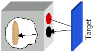
 Laser triangulation sensors are used to make non-contact linear displacement measurements of an object and operate on the following principle: A laser beam (typically from a semiconductor laser) is reflected off a target surface. The returning beam is received and focused onto a CCD sensing array. The CCD array detects the peak value of the light and determines the position of the target based on the position of the beam spot. The sensor produces an analog voltage (typically in the -10v to 10v range) that is proportional to the targets distance from the sensor.
LVDT - Linear Variable Differential Transformers
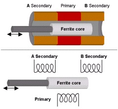
 LVTDs are used to measure the linear displacement and velocity of an object. LVTDs consist of a moving shaft/ferrite material and a set of coils: one primary and two secondary coils. In normal operation, the shaft is connected to an object and an AC magnetic field is introduced on the primary coil. In the centered position, the magnetic flux generated on the primary coil is coupled equally the secondary coils. In this condition, the differential voltage on the secondary coils is zero. When the shaft is moved from its centered position, more of the magnetic flux is coupled to one of the two secondary coils. This results in a positive (or negative) non-zero differential voltage. Using the polarity and magnitude of the voltage, the position of the shaft can be determined.
Tachometer
Tachometers are used to measure the velocity of a rotating object. Tachometers operate on the principle that a driven motor (a motor operated as a generator) produces a voltage that is proportional to the angular velocity of the motor shaft. The proportionality constant, K, that is used to translate mechanical motion into voltage has typical values of 1 to 30 volts per 1000 RPM.
Euclid Research · 2 North 1st Street, 6th Floor · San Jose, CA 95113-1201
Tel: (408) 283-9020 · Fax: (408) 283-9029